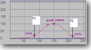
A Slit Diameter (D) is defined as the value of the distance between the two slit positions having a certain amount of the beam peak energy. Generally it is agreed to be 86.5% of the energy of the beam.
The Horizontal Slit diameter can be defined by considering a 1 pixel wide slit and scanning across the image from left to right, and determining the peak energy through that slit. Then repeating the same this time from the left edge of the image, again with a 1 pixel wide slit, scanning across the beam until the slit contains 13.5% of the peak energy, and mark that position as P1.
Again starting from the right side of the image, scanning back across the image until the slit contains 13.5% of the peak energy, and mark that position as P2. The diameter is then the difference between P1 and P2.
D = P2 - P1
The profile in the drawing below represents the energy contained in each pixel column of the image.
X Axis Slit Diameter: D = P2-P1
To determine the Vertical Slit diameter,
perform the same process with a slit that scans from the top of the image
to the bottom.
Knife Edge Measurement
The Knife Edge Widths are widths
in Horizontal (X) and vertical ( Y) axes. ISO standard defines these
as:
The determination of the knife edge width
in the X: starting from the left edge, vertical profiles are summed up until
profile sum is 16% of the total energy. The arrived position is noted
as P1 The next position, P2, is arrived at by continuing the summation from
the position x1 until the sum of the profile is 84% of the total energy. And
these 16%(P1), 84%(P2) locations are the levels specified in the ISO standard.
Due to the flexibility of our 3D Laser Beam Profiler software any energy levels can be defined and it is not restricted to 16 and 84% levels.
By definition, the Knife Edge Widths
are then stated as, for X-axis:
K = 2 * (P2 - P1)
The profile in the drawing below
shows the energy contained in each pixel column of the image.
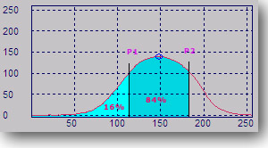
X Axis Knife Edge Diameter: Kx = 2 * (P2 - P1)
The Y axis width is then determined in a similar manner. Except in this case horizontal profiles summing from the top of the image to the bottom of the image need to be operated upon, determining V1 and V2. Note that in this case the summing of horizontal profiles starts from the top of the image to the bottom.
The width is again then twice the difference of the two locations.
Ky = 2 * (V2 - V1)
Naturally depending on the rotational
angle and/or the position of the crosshair an elliptical profile will
be generated and the profiles used to determine the widths will be
parallel to the rotated axes, so the widths will also be parallel to the
rotated axes.
Further details on this subject can be found
in ISO documentation and/or commercial literature.
3D
Laser Beam Profiler Help
Advanced 3D Graphics
-------------------------------------------------------------
Copyright © 2003-2013 ScienceGL, Inc.